Sign in to Guacamole
Guacamole displays a CAE Linux desktop in your browser. The tools run on the CAE machine. Use your own UW NetID and confirm that your account can reach CAE Linux services before the lab.
- On your laptop, open https://guacamole.cae.wisc.edu in a browser.
- Complete the UW web sign-in with your NetID and password, then complete MFA if requested.
- At the Linux login screen, enter your UW NetID and password again. Use your NetID credentials at this second prompt too. The old separate CAE username and password are not the instructions for this service.
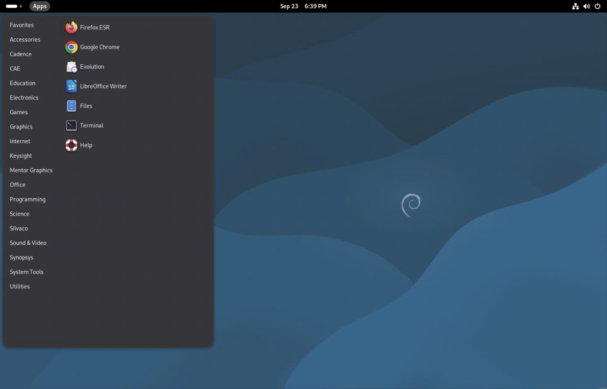
- Wait for the Linux desktop. Open Apps in the upper-left corner and choose Terminal under Favorites. Maximize the terminal by double-clicking its title bar.
- Keep the Guacamole tab open. A terminal inside this desktop is already on CAE; do not SSH back into CAE from it.
If you already have an active session, the browser may reconnect without showing every login screen. If sign-in fails, record which prompt failed: UW web sign-in, MFA, or the Linux desktop login. These are different stages.
More help with Guacamole sign-in, including CAE's official instructions and screenshots: https://kb.wisc.edu/cae/163323
Enter the Synopsys environment
Run these commands in the CAE terminal, one line at a time. Do not type a prompt such as $ or synopsys> before a command.
module load synopsys/suite
synopsys-run
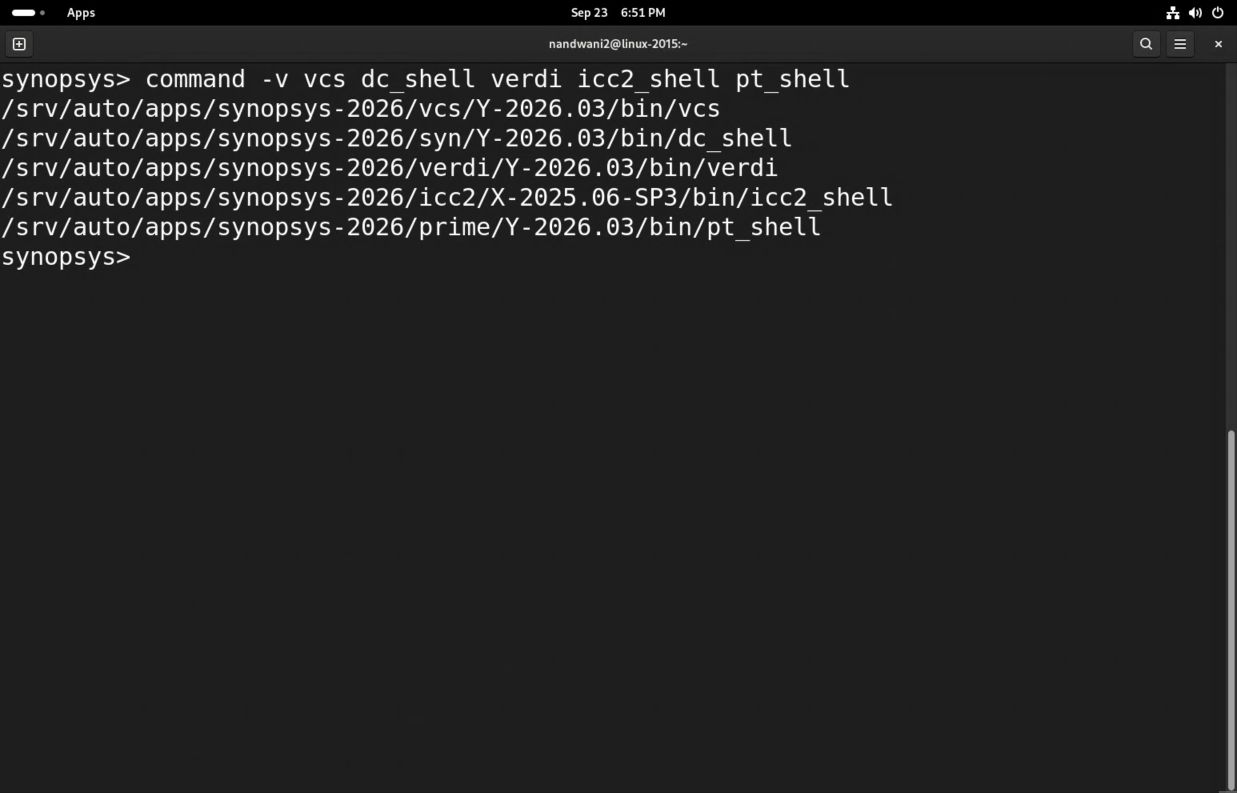
command -v vcs dc_shell verdi icc2_shell pt_shell
The prompt becomes synopsys>. The module selects the site setup; the container provides the operating environment expected by the tools. Load the module before entering the container and repeat this setup for every new terminal used for Synopsys tools.
Companion code
Synthesis runner: https://github.com/abhinavnandwani/cae-synopsys-guides/blob/main/lab/run_lab.py
Synthesis script: https://github.com/abhinavnandwani/cae-synopsys-guides/blob/main/lab/synth/run.tcl
Reference library script: https://github.com/abhinavnandwani/cae-synopsys-guides/blob/main/lab/physical/build_reference.tcl
Floorplan script: https://github.com/abhinavnandwani/cae-synopsys-guides/blob/main/lab/physical/floorplan.tcl
Commands below use ~/cae-synopsys-guides/lab as the exercise directory. The recorded screenshots show the original dated demonstration folder.
Work confidently in the terminal
The current directory affects relative paths. pwd prints it, ls lists files, cd .. moves to the parent, and cd ~/cae-synopsys-guides/lab returns to the exercise. A leading / means an absolute path; ~ means your home directory. Quote paths containing spaces.
| Prompt or location | Commands that belong there |
|---|---|
| Laptop Terminal or PowerShell | ssh to reach the CAE host shell. |
| CAE host shell | module load synopsys/suite, then synopsys-run. |
Container synopsys> | Linux commands, python3 run_lab.py, vcs, verdi, dc_shell, and icc2_shell. |
Tool prompt such as dc_shell> | Tool Tcl commands such as read_ddc, report_timing, and help. |
Use these from the exercise folder to inspect source and logs without changing them:
ls -lh
cat rtl/sb_flop.v
sed -n '1,80p' tb/tb.sv
less runs/YOUR_RUN/compile.log
grep -nE 'Error|Fatal|Warning' runs/YOUR_RUN/compile.log
tail -n 30 runs/YOUR_RUN/simulate.log
Replace YOUR_RUN with an actual directory printed by the runner. In less, use Space to advance, /Error then Enter to search, n for the next match, and q to return to the shell. An Up-arrow recalls a command; Tab completes a path. Read a command before rerunning it.
For an interactive foreground command that is stuck, Ctrl+C requests interruption. For a GUI launched with &, close the application through its File menu. jobs lists jobs started by that shell. Keep logs: command > run.log 2>&1 sends both standard output and errors to a file. Immediately after a command, echo $? reports its exit status, but a zero status alone does not prove the design passed.
Connect without the browser when useful
For terminal-only work, open a terminal on your laptop and run ssh YOUR_NETID@best-tux.cae.wisc.edu, then load the module and enter the container as above. Use Guacamole for the GUI steps in this handout. SSH and Guacamole may reach different hosts, but your CAE home directory is shared.
When finished, save work, close the EDA applications, and run exit to leave the container. Log out of the Linux desktop from the upper-right system menu. Closing the browser alone can leave the session running during CAE's two-hour reconnection window.
Run synthesis and inspect the outputs
From the exercise folder inside the Synopsys container:
python3 run_lab.py synthesisThe runner creates a fresh directory, selects the installed teaching library, calls dc_shell -f synth/run.tcl, and checks diagnostics, the completion marker, and required files. Change into the exact directory printed as RUN_DIRECTORY.
less synthesis.log
cat area.rpt
cat timing.rpt
cat constraints.rpt
cat constraints.sdc
cat mapped.v| Output | What it tells you |
|---|---|
synthesis.log | Tool version, source loading, linking, compilation, and diagnostics. |
mapped.v | Structural netlist using cells in the selected library. |
mapped.ddc | Design Compiler database for resuming inspection in Design Vision. |
constraints.sdc | Exported timing intent, including clocks and I/O delays. |
area.rpt | Cell count and mapped cell area, plus any estimated interconnect area. |
timing.rpt | Reported path, arrival time, required time, and slack. |
constraints.rpt | Constraint violations reported by this run. |
The tested one-register run has two mapped cells and cell area 7.116032 in the library's area units. Its default maximum-delay report has slack 8.86 ns. The report's total area includes an interconnect estimate; it is not a routed core area. Do not compare these numbers with another run without checking library, corner, constraints, and implementation stage.
Read the synthesis script
From the exercise root, open synth/run.tcl. The runner supplies SB_RTL and SB_TARGET_LIBRARY as absolute paths. target_library controls available mapping cells; link_library controls reference resolution. The script reads RTL, selects sb_flop, links, creates a clock and I/O delays, compiles, checks the design, and exports the results.
Make timing assumptions explicit
The teaching constraints are deliberately simple:
create_clock -name clk -period 10 [get_ports clk]
set_input_delay 1 -clock clk [get_ports {rst d}]
set_output_delay 1 -clock clk [get_ports q]
The period is 10 ns. The input delay reserves time for the external launch side; the output delay reserves time for the external capture side. These values are assumptions for this example. Constraints for other designs may also need generated clocks, input transition, output load, uncertainty, exceptions, and operating scenarios.
Use these Tcl commands in dc_shell or Design Vision after loading the design:
check_design
check_timing
report_clock
report_timing -delay_type max -max_paths 5
report_timing -delay_type min -max_paths 5
report_constraint -all_violators
report_area
check_design asks structural questions; check_timing helps reveal missing or inconsistent timing setup. Maximum-delay and minimum-delay checks answer different questions. For a setup path, slack is required time minus arrival time; for a hold path the relationship is different. Always identify the analysis type before interpreting the sign and number.
Read one path completely
Start with the startpoint and endpoint, then identify the clock and path group. Follow the cell and net contributions to data arrival time. Read the required time and slack. In the recorded example, the path starts at rst, ends at the mapped register, and reports arrival 1.01 ns, required 9.88 ns, and slack 8.86 ns after rounding.
Positive slack for this path does not show that every intended path exists or is constrained. Pre-layout timing also lacks the final physical parasitics and clock tree. Keep a stage label on every report: mapped synthesis, placed, post-clock-tree, or routed.
Load the mapped design in Design Vision
In Guacamole, launch design_vision from the synthesis run directory. Maximize the window and wait for startup to complete. At the bottom Tcl input line, enter:
set edk /srv/auto/apps/saed32_edk/2023/lib/stdcell_rvt
set dbdir "$edk/SAED32_EDK/lib/stdcell_rvt/db_nldm"
set lib "$dbdir/saed32rvt_tt1p05v25c.db"
set_app_var target_library [list $lib]
set_app_var link_library [concat * $target_library]
read_ddc mapped.ddc
current_design sb_flop
link
read_sdc constraints.sdc
check_design- Read the console after each command. Resolve missing library or unresolved-reference errors before drawing conclusions.
- Select
sb_flopin Logical Hierarchy, then choose Schematic, New Schematic View. - Double-click the module boundary box to expand the mapped contents.
- Choose View, Zoom, Zoom Fit All. Collapse an unused pane to give the schematic more width; double-click its bottom tab to restore it.
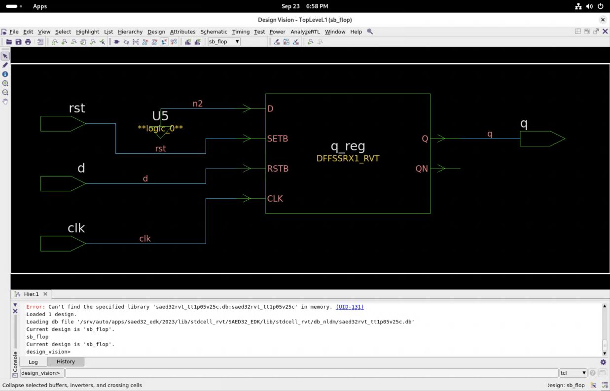
Trace the boundary ports to the mapped cells. Inspect q_reg and compare its pin connections with mapped.v. Synthesis can use library-specific transformations, so the cell's actual function matters. A schematic confirms connectivity and mapping choices; it does not replace formal equivalence or functional verification.
Generate and investigate timing in the GUI
Choose Timing, Report Timing Path. Start with max delay, full path type, one worst path per endpoint, and one path per group. Leave From, Through, and To empty for the initial report, and enable To report viewer.
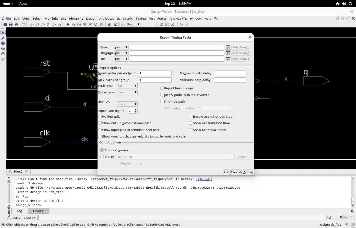
- Click OK and allow the report pane to populate. Confirm the design, startpoint, endpoint, path group, and delay type.
- Read the complete path through arrival time, required time, and slack. Scroll the report if necessary; the first screen may not contain the final slack line.
- Use linked object names in the report and the schematic to locate the cell or net under investigation.
- Return to the timing dialog to narrow From or To when investigating a specific interface or register. Repeat with minimum delay when investigating hold behavior.
- Read the generated Tcl command in the console. Preserve the equivalent command in the run script so the report can be regenerated outside the GUI.
For larger text, use View, Preferences, Style Settings. Normal controls interface labels and Monospace controls report text. Enlarge the pane as well as the font. Save reports from Tcl with redirect -file focused_timing.rpt {report_timing -max_paths 5}.
Understand the inputs to physical implementation
ICC2 needs physical technology and cell abstracts in addition to logical timing models. A successful dc_shell run using a .db does not establish that the physical setup is complete.
| Input | Purpose |
|---|---|
| Technology file or technology library | Layers, routing geometry, sites, and physical rules used by implementation. |
| Reference cell library | Physical cell abstracts, pins, and logical/timing views, normally packaged as NDM for ICC2. |
| Mapped netlist | Instances and connectivity to implement. |
| SDC and scenario setup | Clocks, interface budgets, exceptions, and analysis conditions. |
| RC technology | Parasitic modeling appropriate to the implementation and extraction flow. |
| Floorplan and power intent | Die/core geometry, macros, pins, power nets, and applicable domain requirements. |
The accessible CAE SAED32 EDK contains the timing .db, standard-cell LEF, and a Milkyway technology file used by this teaching exercise. The separate SAED32 PDK directory returned permission denied for the tested account. These are different paths. Keep licensed library data on CAE; the companion package contains scripts referencing installed data, not copies of that data.
The teaching corner is RVT, TT, 1.05 V, 25 C. Area and timing results depend on the library, corner, parasitic assumptions, and constraints used for the run.
Prepare the teaching reference library from the terminal
Finish the synthesis exercise first. In a container shell, set the successful run directory and create a separate physical run:
SB_LAB="$HOME/cae-synopsys-guides/lab"
export SB_SYNTH_RUN="$SB_LAB/runs/YOUR_SYNTHESIS_RUN"
SB_PHYS=$(mktemp -d "$SB_LAB/runs/physical-XXXXXX")
cd "$SB_PHYS"
icc2_lm_shell -f "$SB_LAB/physical/build_reference.tcl" \
  > library.log 2>&1
less library.log
Replace YOUR_SYNTHESIS_RUN with the actual directory. The script runs in Library Manager, whose prompt is lm_shell>. It creates a workspace using the installed technology file, reads the timing .db and cell LEF, checks the workspace, and writes sb_rvt.ndm in this private run directory.
set edk /srv/auto/apps/saed32_edk/2023
set cells $edk/lib/stdcell_rvt/SAED32_EDK/lib/stdcell_rvt
create_workspace -technology $edk/tech/milkyway/saed32nm_1p9m_mw.tf \
  -flow normal sb_rvt
read_db $cells/db_nldm/saed32rvt_tt1p05v25c.db
read_lef $cells/lef/saed32nm_rvt_1p9m.lef
check_workspace
commit_workspace -output sb_rvt.ndm
The tested workspace check succeeded and created 294 frames. Its diagnostics included a technology-layer warning, a LEF bus-character warning, and warnings about large M1 routing blockages in cell abstracts. Preserve and review them. Successful import does not certify the library for routing or signoff.
Keep library.log with the run. Stop if the workspace check fails or the NDM output is missing. Do not copy the generated reference library into a public repository or the handout package.
Import and floorplan the register in ICC2
In the same physical run directory, run:
icc2_shell -f "$SB_LAB/physical/floorplan.tcl" \
  > floorplan.log 2>&1
less floorplan.log
grep -nE 'Error|Warning|REGISTER_|FLOORPLAN_DONE' floorplan.log
The script creates sb_flop.dlib, imports the mapped netlist, links the design against the reference NDM, reads the SDC, initializes a small die and core, makes an initial floorplan placement, and saves the block and library. The corresponding interactive Tcl commands are:
create_lib -ref_libs {sb_rvt.ndm} sb_flop.dlib
read_verilog -top sb_flop $env(SB_SYNTH_RUN)/mapped.v
link_block
read_sdc $env(SB_SYNTH_RUN)/constraints.sdc
initialize_floorplan -control_type die \
  -boundary {{0 0} {20 20}} -core_offset 2
create_placement -floorplan
get_attribute [get_cells q_reg] origin
get_attribute [get_cells q_reg] physical_status
save_block
save_lib
The boundary and offset are teaching dimensions in the technology's distance units. The tool snaps the core to the site rows. This tiny design deliberately leaves plenty of empty space.
Check the successful-link message, floorplan-completion message, cell location/status, and saved files. The tested technology also prompted ICC2 to derive missing preferred routing directions. Review that setup before attempting routing. The completion marker only means the script reached its end; errors earlier in the log still need attention.
Open and inspect the physical design in the GUI
Start icc2_shell in the physical run directory. At its Tcl prompt, reopen the saved design:
open_lib sb_flop.dlib
open_block sb_flop
start_gui
If the block is already open in the same session, use only start_gui. Maximize the IC Compiler II window. Its title should identify sb_flop.dlib:sb_flop.design. Check that title before inspecting or editing anything.
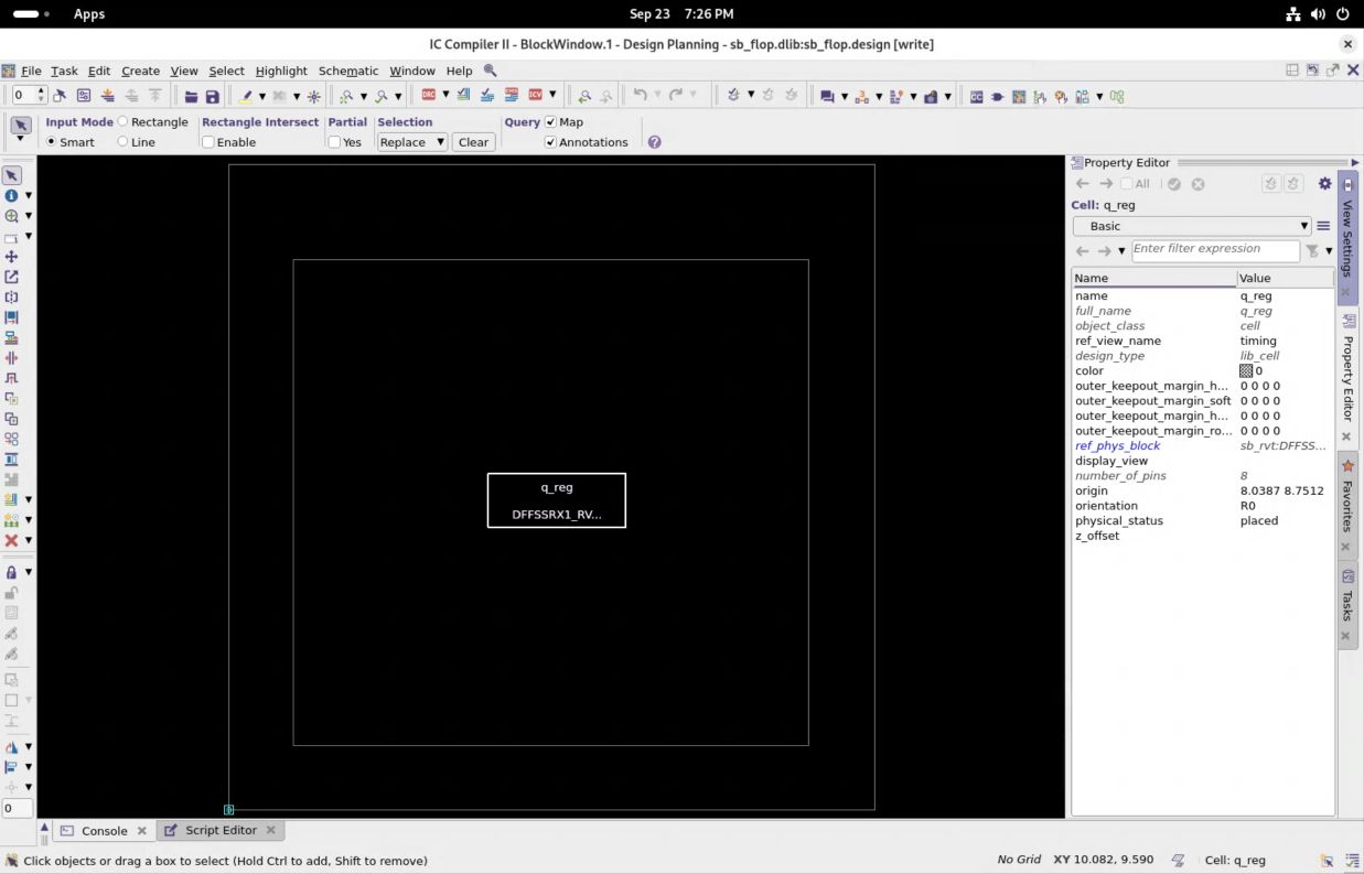
- Identify the outer die boundary and the inner core boundary. The core is inset from the die and aligned to the placement sites.
- Find the rectangle labelled
q_reg. Click it once to select the cell, then open the Property Editor tab on the right. - Read its name, reference view, origin, orientation, and
physical_status. The recorded initial placement reportsplaced; this is not a statement that detailed legalization or routing checks passed. - Compare the selected instance with
mapped.v. The logical netlist, physical abstract, and timing view must refer to compatible cells and pins. - With the cell selected, choose View, Zoom, Zoom Fit Selection. Choose Zoom Fit All to recover the overview. The right-side View Settings panel controls visible objects and layers. Hiding an object does not remove it from the design.
The empty space and absence of a routed interconnect network are expected at this stage. An initial floorplan placement is useful for learning selection, geometry, and database inspection. It is not a finished physical design.
Connect GUI observations to repeatable commands
The Property Editor provides concrete database attributes. Use the tool console to query the same selected design objects explicitly:
get_attribute [get_cells q_reg] origin
get_attribute [get_cells q_reg] orientation
get_attribute [get_cells q_reg] physical_status
get_object_name [get_pins q_reg/*]
The recorded cell origin was approximately {8.0387 8.7512}, orientation R0, and physical status placed. Coordinates can change when the floorplan or placement settings change; compare the geometry and status with the run you actually opened.
When a larger design is difficult to navigate, select an object by its name or query it in the console before zooming and tracing its connections. Confirm both the instance name and reference cell. A similarly named cell in another hierarchy is a different object.
Inspect messages as part of GUI use. Open the Console tab at the bottom and use View, Error Browser for diagnostics. Start from the first relevant setup error. Check the saved run log when the GUI only shows the most recent messages.
Save a checkpoint and know what remains
After an intentional change, save the block and library using save_block and save_lib. Keep the script and log that produced that state. Reopening the saved block is a useful check that the result is reproducible beyond the current GUI session.
The demonstrated physical exercise ends after import, floorplan initialization, and initial placement. It has not built a power grid, assigned a final pin plan, performed detailed legalization, constructed the clock tree, routed signals, extracted final parasitics, or passed signoff checks.
Do not hide a warning by suppressing it just to get a cleaner screenshot. Record whether it is a teaching-library limitation, a missing flow input, or a real design problem. Separate those from the measured outcomes of a completed implementation stage.
Troubleshoot by stage
For synthesis, start with source loading, top selection, linking, and constraints. For physical import, start with technology and reference libraries, cell/pin resolution, and netlist consistency. For placement, inspect sites, floorplan geometry, legal cell locations, and power connectivity before tuning optimization options.
If a license check fails, save the exact tool diagnostic and version. If a GUI appears unresponsive during launch, allow startup to complete before starting another copy. If a command is unfamiliar, use help -verbose command_name or man command_name in the tool version you are running.
Close GUI tools, save your checkpoints, leave the container, and log out of the CAE desktop when finished. Design Compiler and Design Vision were exercised on Y-2026.03; ICC2 uses X-2025.06-SP3 on this CAE installation.
Setup: https://kb.wisc.edu/cae-software-guide
ICC2 capabilities: https://www.synopsys.com/implementation-and-signoff/physical-implementation/ic-compiler.html